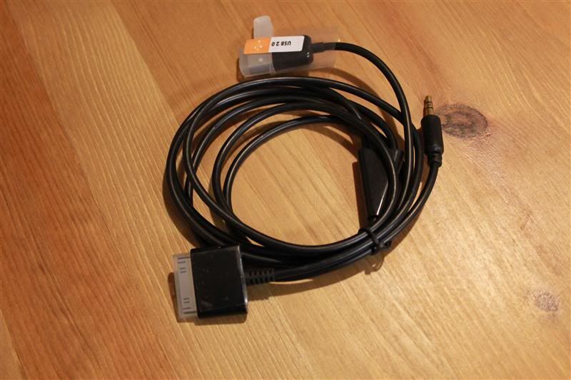
I just made my own "car dock" cable based on the information over the "Fun with resistors" thread.
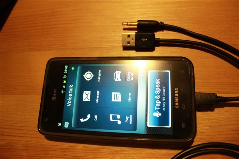
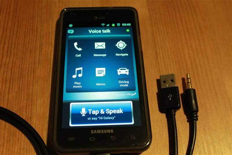
Basically I have a cable with a micro-usb connector that switch my phone to "car dock" mode, audio via usb/aux and charging.
CHECK THE 2ND POST FOR UPDATES, PICTURES AND A QUICK VIDEO.
This is the pin-out for the usb connector:

Preparations:
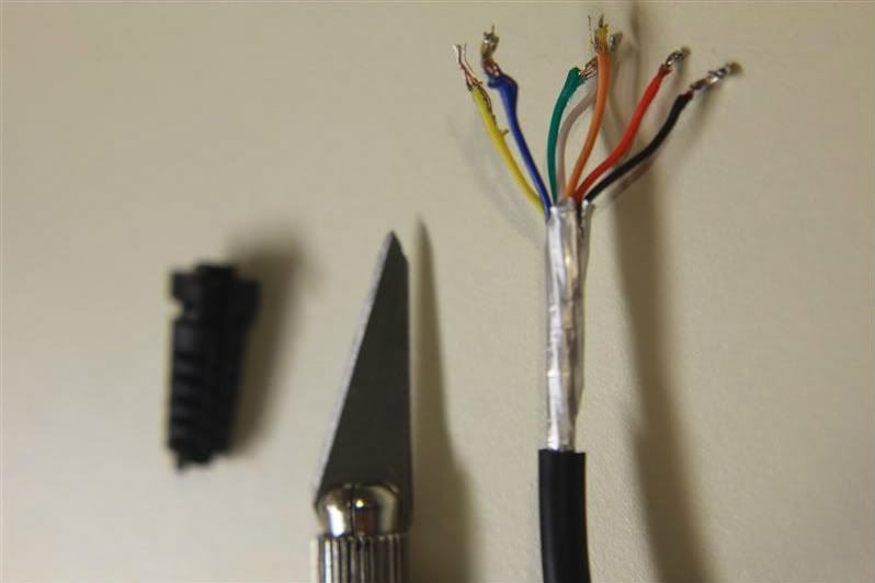
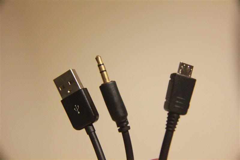
1) Cut one of the aux cable connectors and expose the 3 wires:
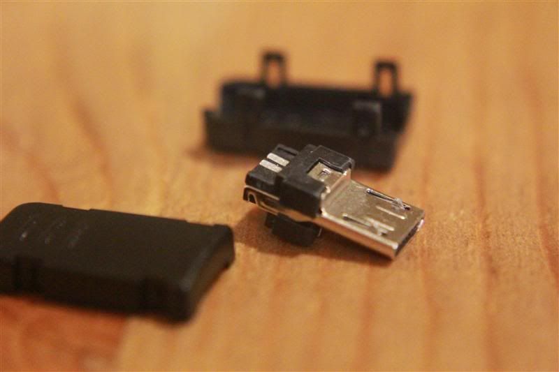
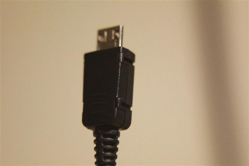
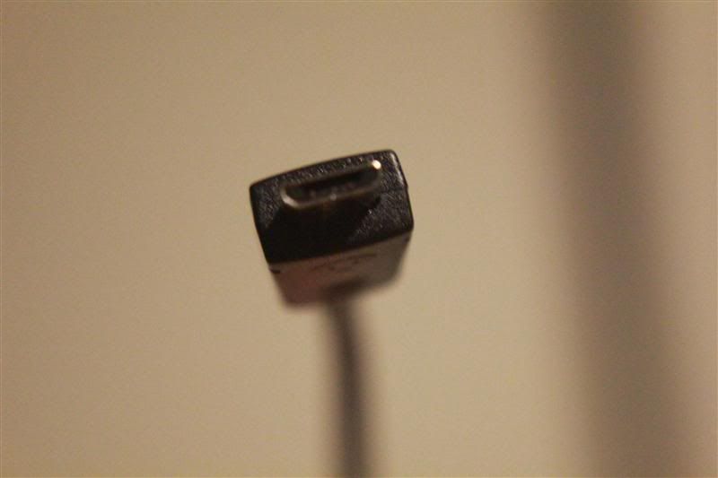
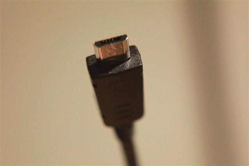
2) Cut the micro usb connector from the usb cable and expose the 4 wires:
Soldering:
Start with the audio cable:
Now with the usb cable:
With the resistor:
Almost done...
I will post pictures next week when I will make a new cable with longer usb and better finish.
The cable I have now works fine, it's just ugly...
I hope this info will be useful for someone
Thanks to TheBeano for the info about the resistors
Basically I have a cable with a micro-usb connector that switch my phone to "car dock" mode, audio via usb/aux and charging.
CHECK THE 2ND POST FOR UPDATES, PICTURES AND A QUICK VIDEO.
WARNING:
Parts that I used:- This cable can physically damage/destroy your phone if made incorrectly.
- If you don't have experience soldering electronics and small parts maybe you should not try this.
- The usb cable will NOT work for sync/data - just charging.
- I'm not responsible if you damage or destroy your phone/property and/or injury yourself or others.
- Use this instructions at your own risk.
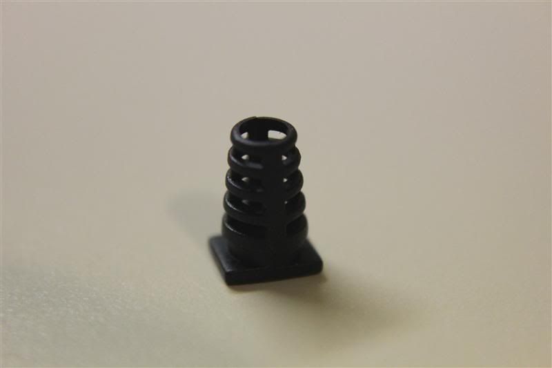
- micro usb male connector (Digi-Key pn: 609-4051-ND)
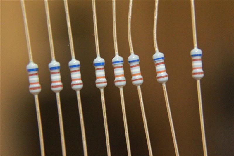
- 619K ohm resistor (Digi-Key pn: RNF14FTD619KCT-ND)
- 6ft 3.5mm Stereo Plug/Plug M/M Cable (MonoPrice.com pid: 644)
- 1.5ft USB 2.0 A Male to Micro 5pin Male 28/28AWG Cable (MonoPrice.com pid: 5137)
I should have used a longer cable but that's what I had at home
This is the pin-out for the usb connector:
Preparations:
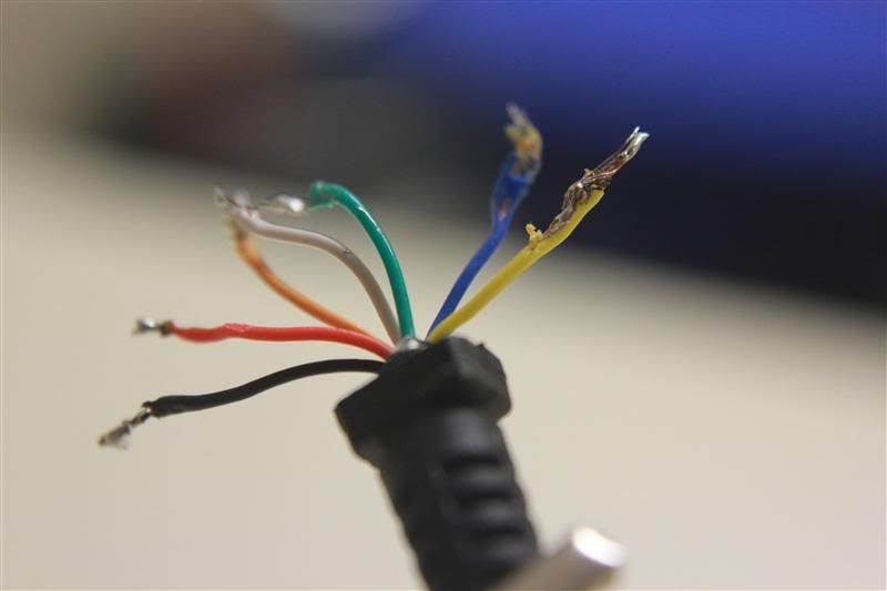
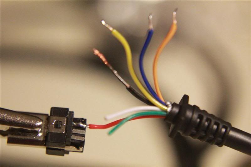
1) Cut one of the aux cable connectors and expose the 3 wires:
- Yellow = common ground
- White = right channel
- Red = left channel
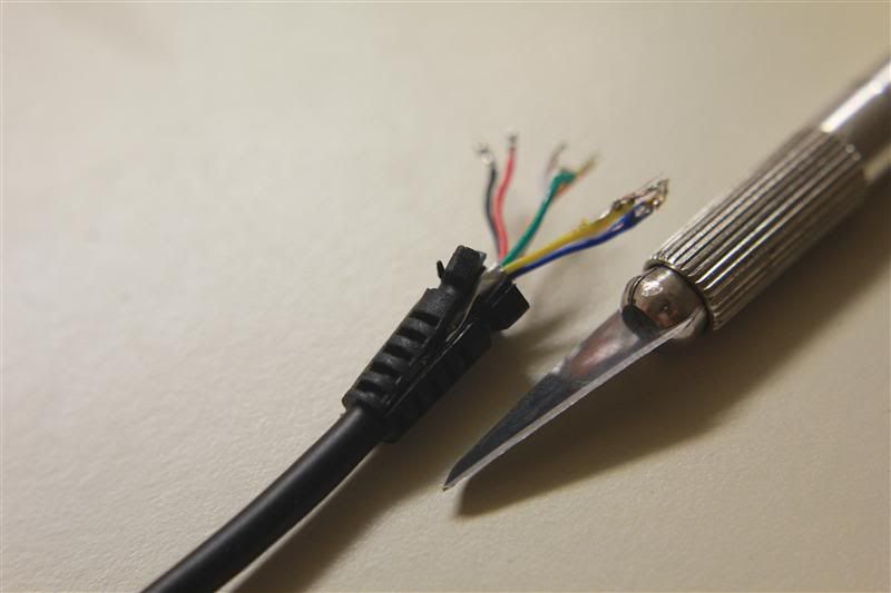
2) Cut the micro usb connector from the usb cable and expose the 4 wires:
- Red = +5vcc
- Black = ground
- Green = not used
- White = not used
Soldering:
Start with the audio cable:
- Solder left channel wire to pin 2
- Solder right channel wire to pin 3
- Do NOT solder the ground wire yet
Now with the usb cable:
- Solder red wire wire to pin 1
- Do NOT solder the ground (black wire) yet
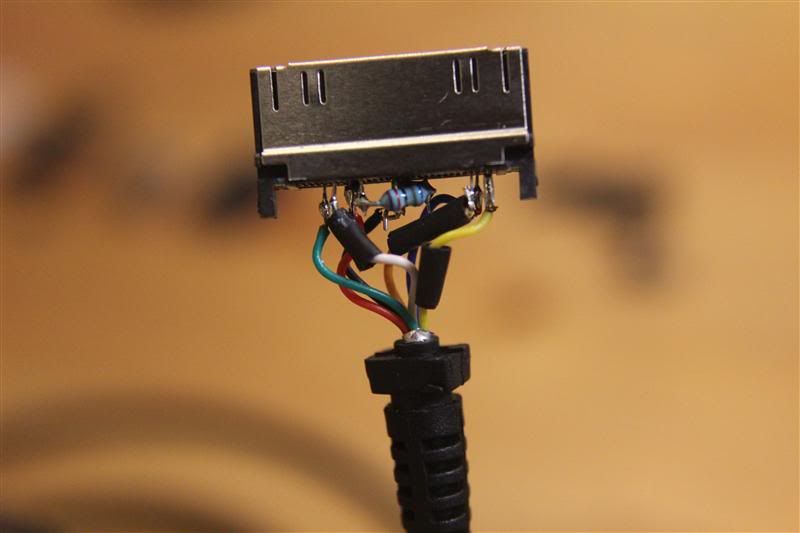
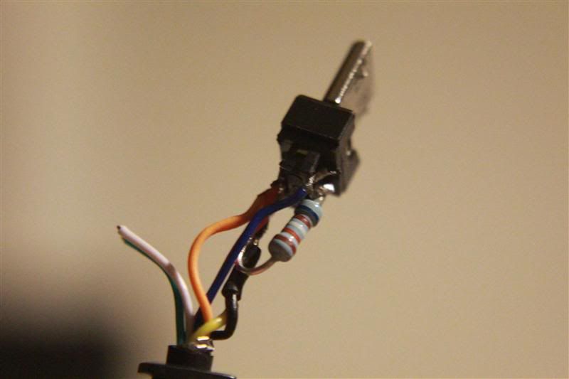
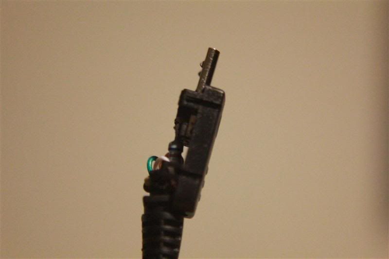
With the resistor:
- Solder 1 resistor leg to pin 4
- Solder the other resistor leg + audio ground (yellow wire) + usb ground (black wire) to pin 5
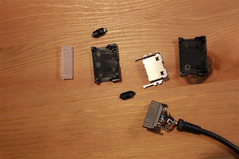
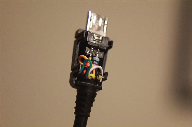
Almost done...
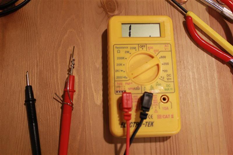
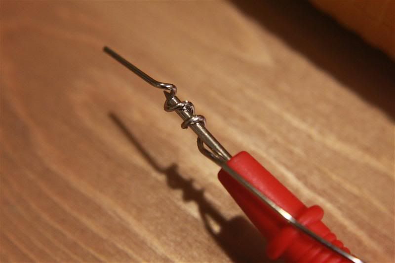
- Test all the connections for short-circuit with a digital multimeter
- Triple check for the right cable on the right place, you don't want to put that +5vcc on the wrong pin, it will fry your phone!
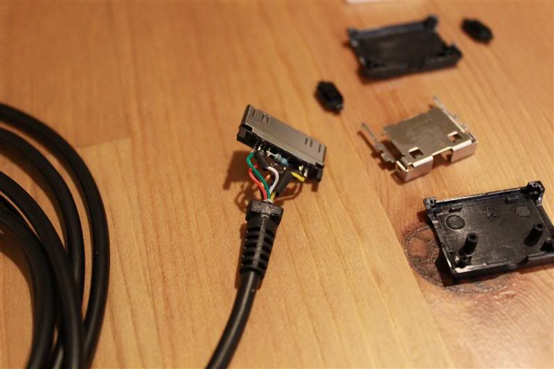
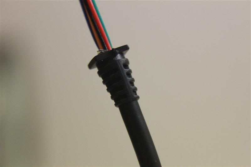
- Just finish it with some epoxy glue to make sure the cables won't break where you soldered them and some shrink tube for a polished finish.
- You must go to Settings > Dock Settings > Audio output mode and enable it to have the audio-out working.
I will post pictures next week when I will make a new cable with longer usb and better finish.
The cable I have now works fine, it's just ugly...
I hope this info will be useful for someone
Thanks to TheBeano for the info about the resistors
Last edited: